5. The NOT logic gate
The simplest components of digital electronics are logic gates, which carry out basic logical operations. By combining these logic gates you can build much more complex circuits, up to modern computers.
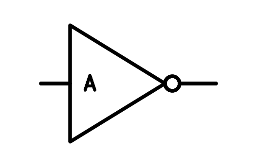
The simplest possible logic gate is the negation gate, also called inverting gate or NOT gate, whose symbol is shown below:

NOT logic gate.
This gate inverts the value of the input signal, so that if the input is a logic 1, the output will be a logic 0 and vice versa.
The circle at the exit of the triangle is the one that represents that the door inverts, or negates, the input value.
The logical function NOT is represented by a line over the element to be inverted or negated:
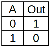
Next we can read the truth table of the NOT gate, which represents all the possible input and output values of the logic gate:

Truth table of the NOT logic gate.
When the input (A) is zero, the output (Out) will be one.
When the input (A) is one, the output (Out) will be zero.
Simulation
In the following simulation we can see a NOT gate with an input that can change value and an output that is always the opposite of the input value.
In the simulator the values can be represented with numbers (0, 1), with logic levels (L, H) or with voltage values (0V, 5V), with the following correspondence:
| Level | Logical value | Voltage value |
|---|---|---|
| L = LOW | 0 = Logical zero | 0 Volts |
| H = HIGH | 1 = Logical one | 5 Volts |
You must click on the input logic value to change its value.
Exercises
What is a logic gate? What can be built with logic gates?
Draw the NOT gate symbol and write below its logical function and its three different names.
Draw the truth table of the NOT gate with numeric values.
Draw the truth table of the NOT gate with logical levels.
Perform a simulation of two NOT gates in series. What do you think the two-door truth table will be like?
Perform the simulation and draw the truth table of the two gates in series.