4. Pushbuttons and LEDs
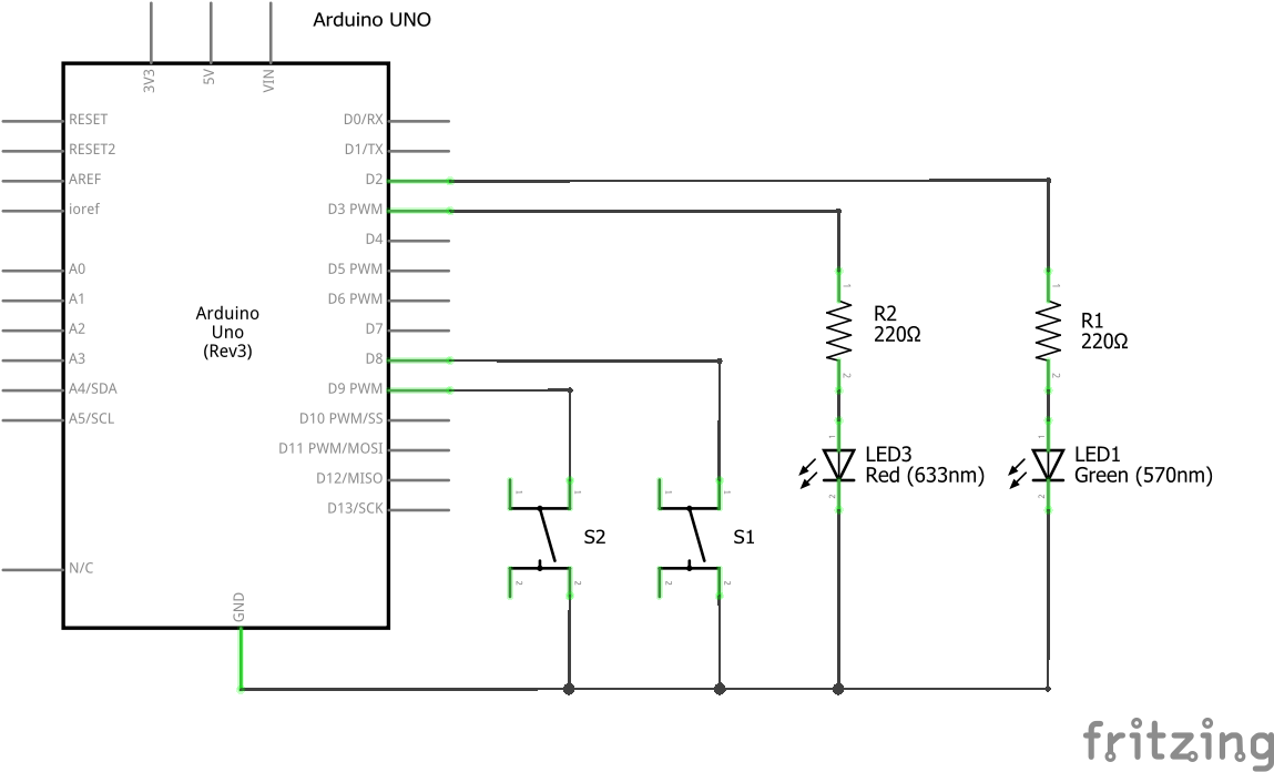
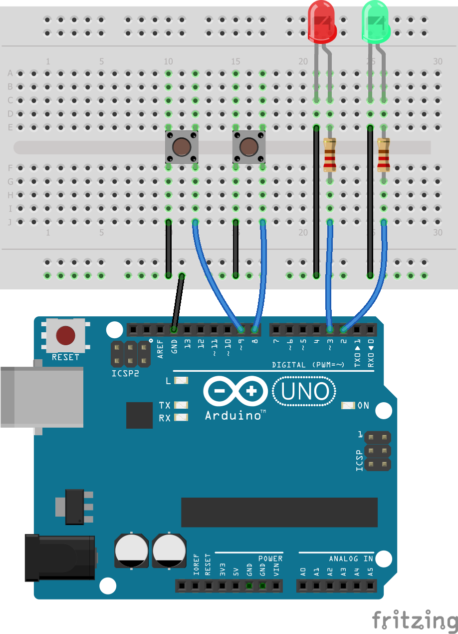
Mount the following electrical schematic on a breadboard.


Electrical circuit in Fritzing format
Exercises
Upload the following program to the Arduino UNO board. The green led will light up when pressing button 1.
 1
 2
 3
 4
 5
 6
 7
 8
 9
10
11
12
13
14
15
16
17
18
19
20
21
22
23
24
25
26
27
28
29
30
// Define el pin de cada componente
int LED_VERDE = 2;
int LED_ROJO = 3;
int PUSH_1 = 8;
int PUSH_2 = 9;

// Ejecuta una sola vez las siguientes instrucciones
void setup() {
   // Los ledes se conectan a salidas
   pinMode(LED_VERDE, OUTPUT);
   pinMode(LED_ROJO, OUTPUT);

   // Los pulsadores se conectan a entradas
   pinMode(PUSH_1, INPUT_PULLUP);
   pinMode(PUSH_2, INPUT_PULLUP);
}

// Repite para siempre las siguientes instrucciones
void loop() {
   // Si presionamos pulsador 1 entonces
   if (digitalRead(PUSH_1) == LOW) {
      // Enciende el led verde
      digitalWrite(LED_VERDE, HIGH);
   }
   // En caso contrario
   else {
      // Apaga el led verde
      digitalWrite(LED_VERDE, LOW);
   }
}
Modify the previous program to add that the red led turns on when pressing button 2.
Modify the previous program so that the two LEDs light up when you press button 1 and that they go off when you press button 2.
Write a program to simulate a timed staircase light. The green led will light up when button 1 is pressed and it must stay on for 4 seconds. After that time the green led will turn off.
The instruction to use to wait four seconds is:
1
delay(4000);
Modify the previous program so that the red led is on while the green led is off and it turns off when the green led is on.